| HP-41C Thermal Printer Refurbishment |
|
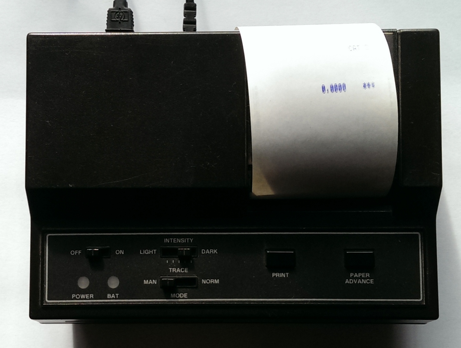
The Thermal Printer, HP item number 82143A, plugs into one of the
expansion connectors at the top of the HP-41C calculator. The Archive's printer was obtained cheaply as an untested item for spares or repair. A quick examination showed that the printer was in good cosmetic condition and that the battery pack showed no signs of leakage. The battery pack would also take a full charge and this lasted quite a while. A quick test showed that the printer was functional but not working correctly in that the paper was not pulled through smoothly, causing the print to squash vertically. Horizontally it was good. The thermal print head was also working properly over the whole line width.
|
|
|
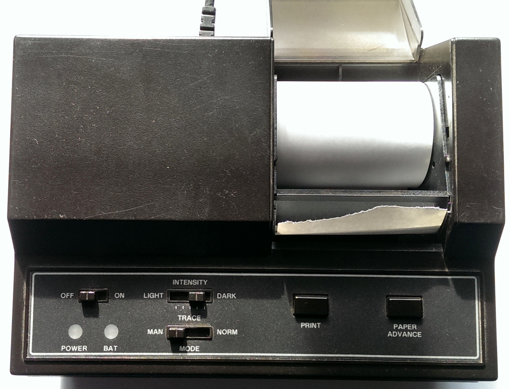
| This view shows the printer output. The digits appear to be 'dithering' due to the inaccurate line feed. The top view shows the good cosmetic appearance.
|
|
|
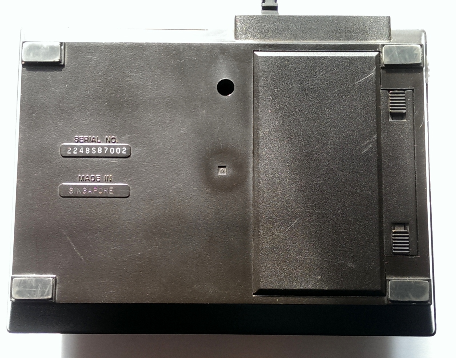
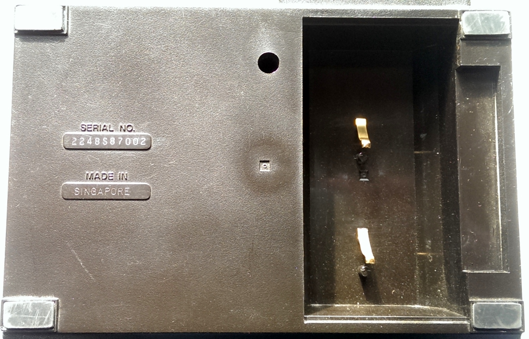
| The underside view reveals the battery compartment access cover, serial number and country of manufacture. A single screw hole is shown. This was one of the screws holding the base to the top; the other screws were beneath the four rubber feet.
|
|
|
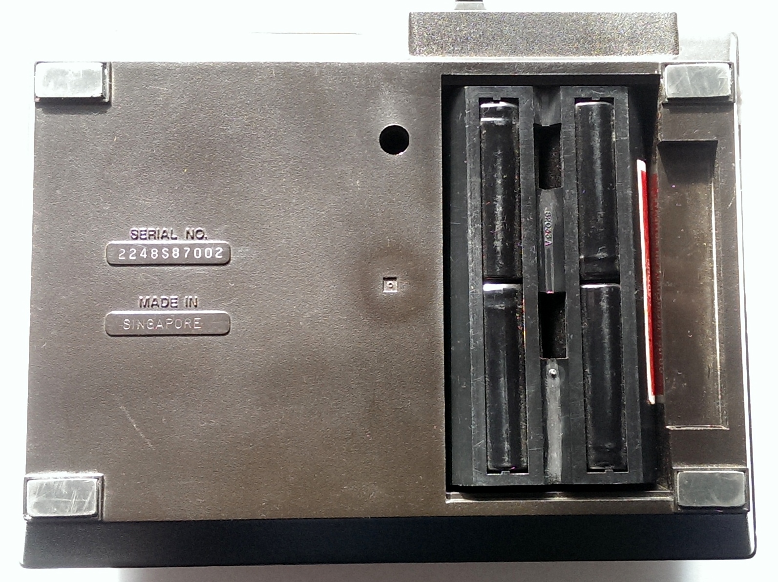
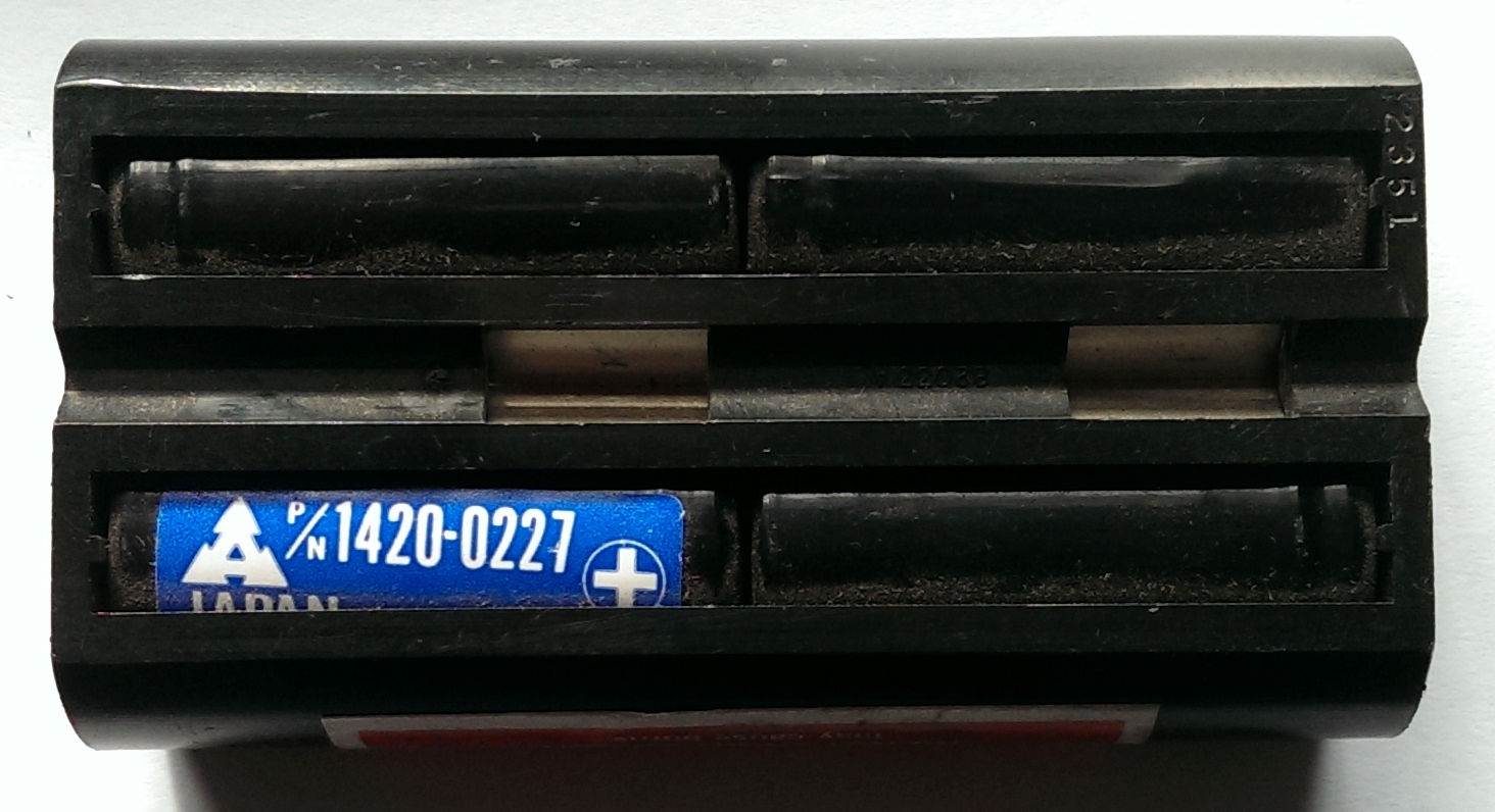
| Removing the battery cover shows the battery in situ. It shows no evidence of leaking and when removed, apart from some light dust, it was in excellent condition.
|
|
|
|
|
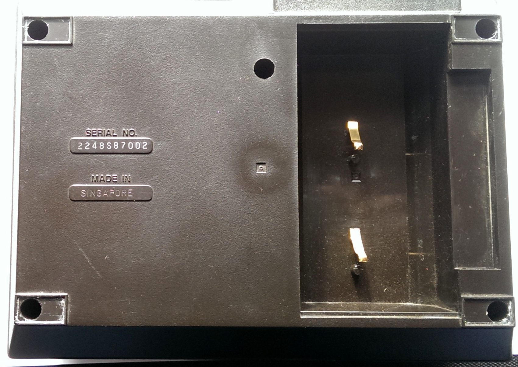
| The battery compartment showed no evidence of leakage and the phosphor bronze contacts were in perfect condition.
|
|
|
| The next stage was to remove the paper roll and then the rubber feet from the underside.
|
|
|
|
|
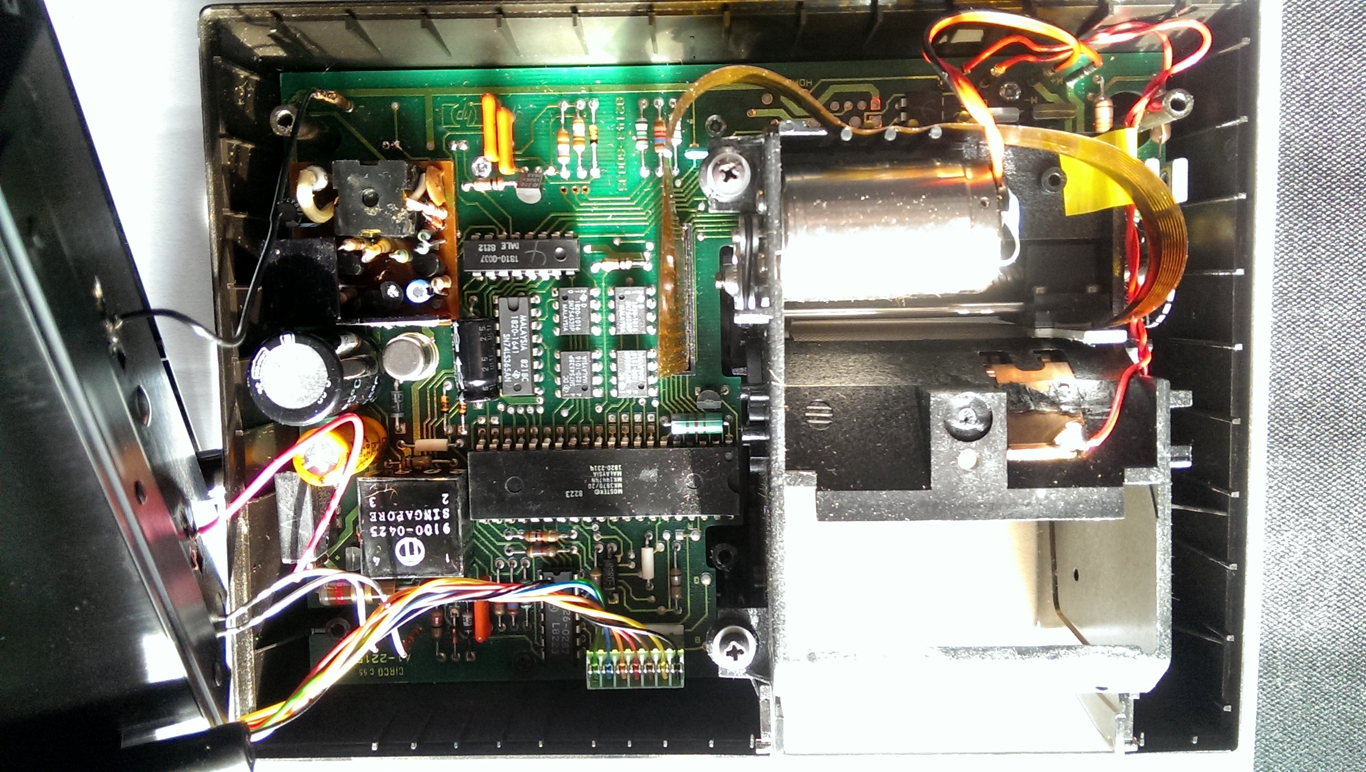
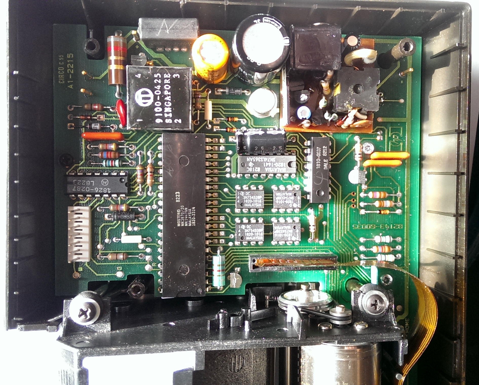
| The main circuit board is fitted to the lid. The base only holds the battery compartment and mains circuitry. The base is easily removed by unplugging the connecting leads. The main circuit board is very complex and boasts its own microprocessor, the MOSTEK MK3870 microcontroller.
|
|
|
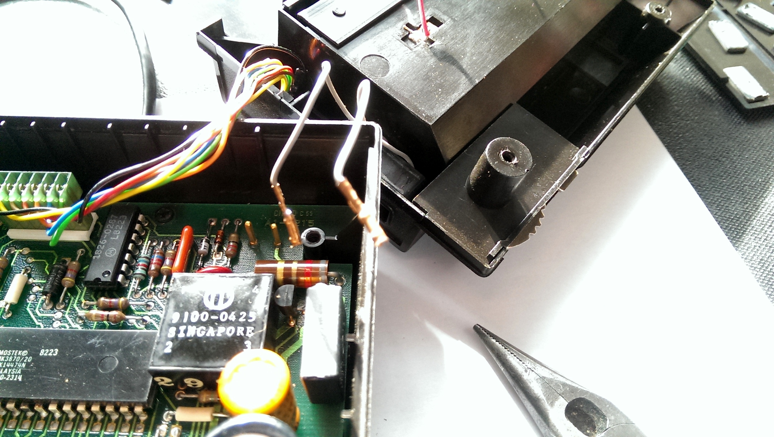
| Once the base has been removed the print head can be removed by undoing the screws holding it in place. These screws pass through rubber grommets, which need to be inspected for damage and replaced as necessary. There is no need to unplug the flexible printed wiring harness or any of the connecting wires. Once loose, the print head can be gently lifted upwards and swung backwards.
|
|
|
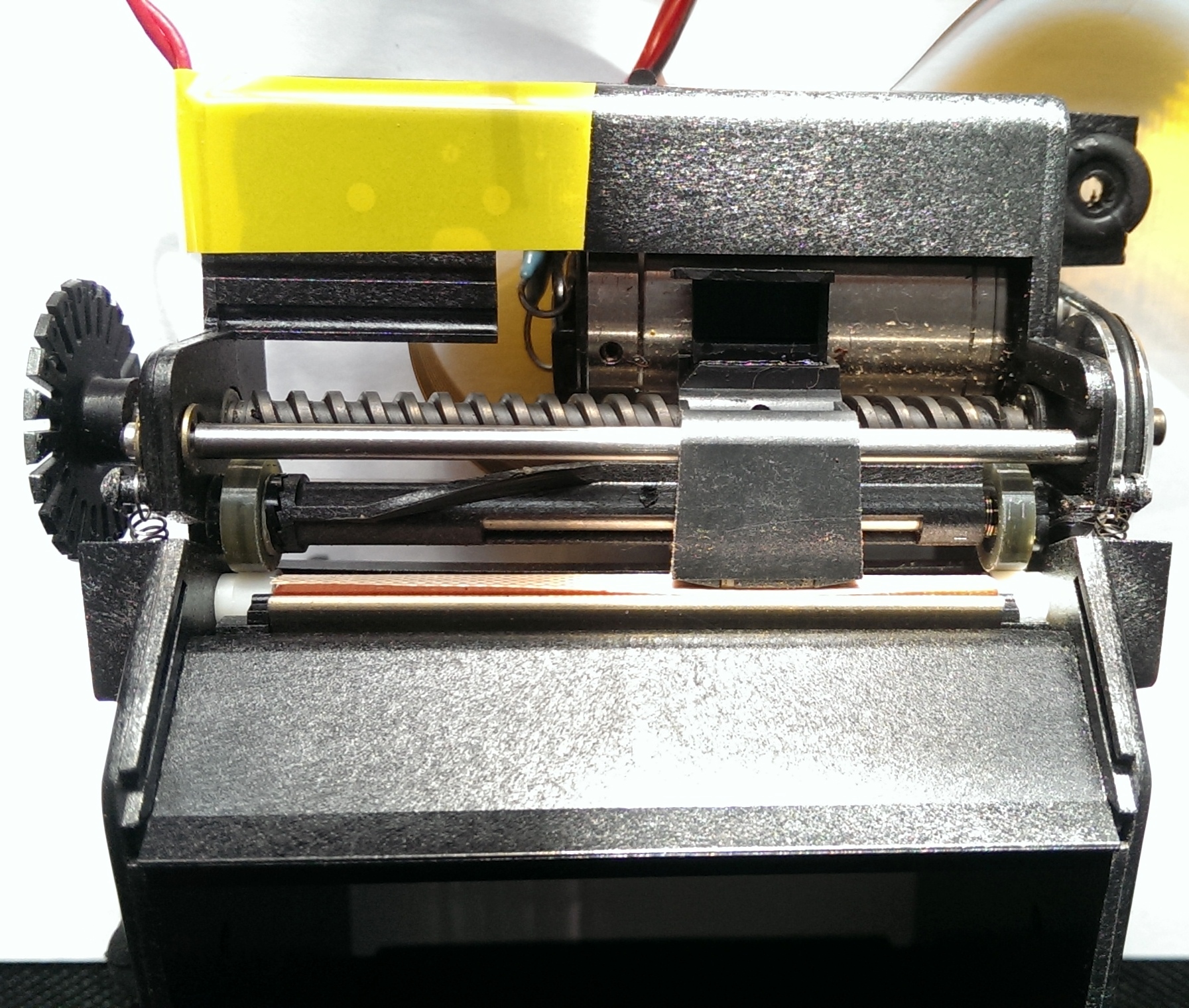
| The picture above shows the print head mechanism. To the left is a slotted wheel which fits into a photo-sensor and allows the microcontroller to determine the line feed accurately. The central helical screw moves the thermal print head left and right. The screw is driven by a belt, shown to the right, feeding from the motor. Below the helical screw is the paper driving mechanism. To each side are soft plastic/silicone wheels. These grip the paper against the white roller and advance the paper one line on the return stroke of the print head, which engages on the plastic fitting on the axle joining the rubber/silicone wheels. The wheels were both dirty and polished, lacking grip. Firstly the wheels were cleaned with an IPA-water mixture to remove the dirt and then slightly roughened using very fine wet and dry paper (shown over the polished rod in the centre). This improved their grip on the paper.
|
|
|
| Finally the printer was reassembled, reversing the method of disassembly. Before replacing the base, the drive belt was replaced. This originally was an O-ring, or so it appeared. A replacement slightly smaller than the one taken off was used. The printer now line fed correctly and gave excellent output. |