|
|
|
Gallery |
 |
|
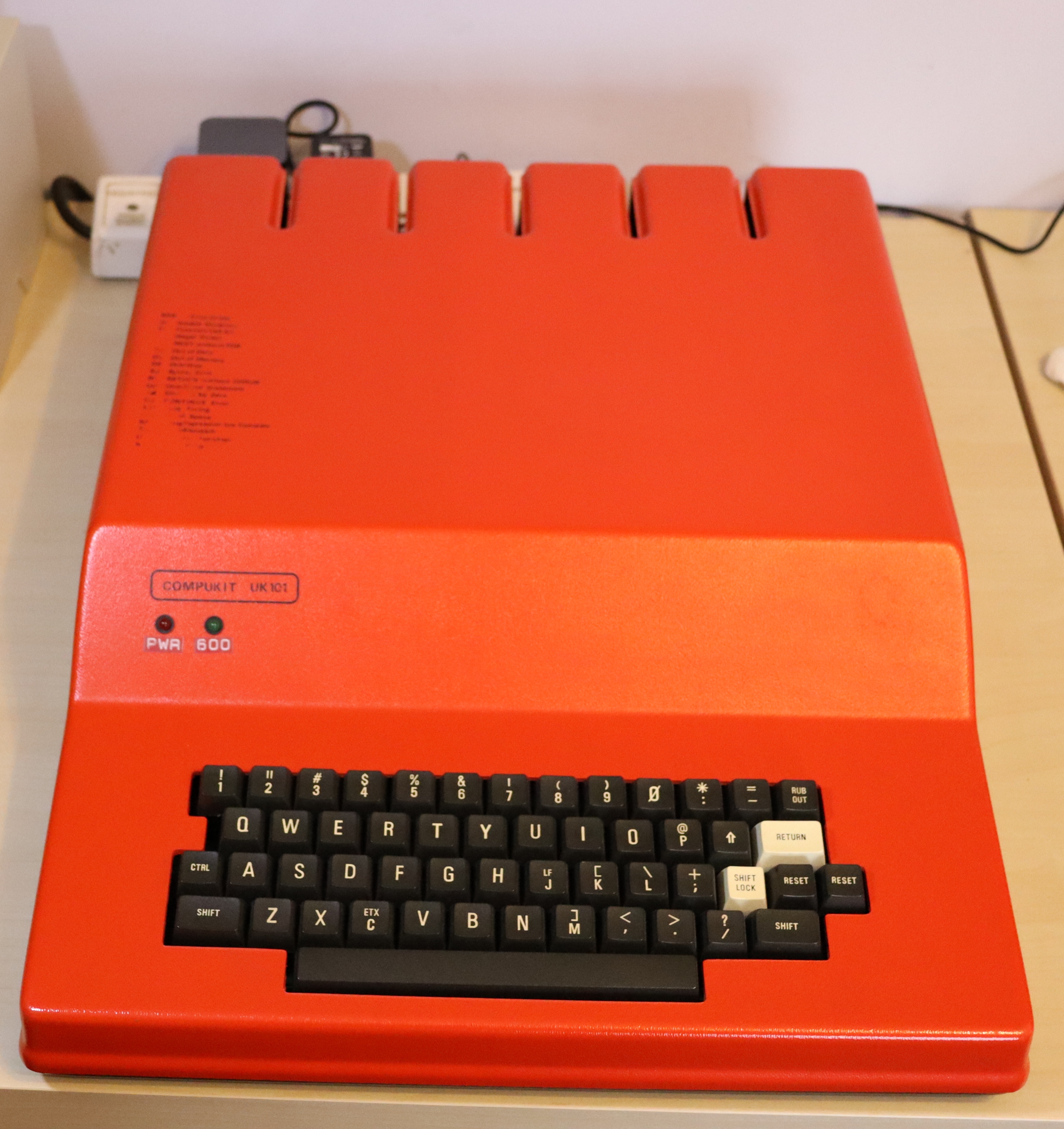
This UK101 was purchased in 2014 complete with the distinctive red case. It was fully working and had 8K of RAM and the 32 lines screen upgrade with a CEGMON monitor ROM. The machine also had a switched 300/600 baud cassette modification fitted. Recently the case had two LEDs added. The red LED indicates when power is on and the green LED indicates 600 baud for the cassette interface. |
 |
|
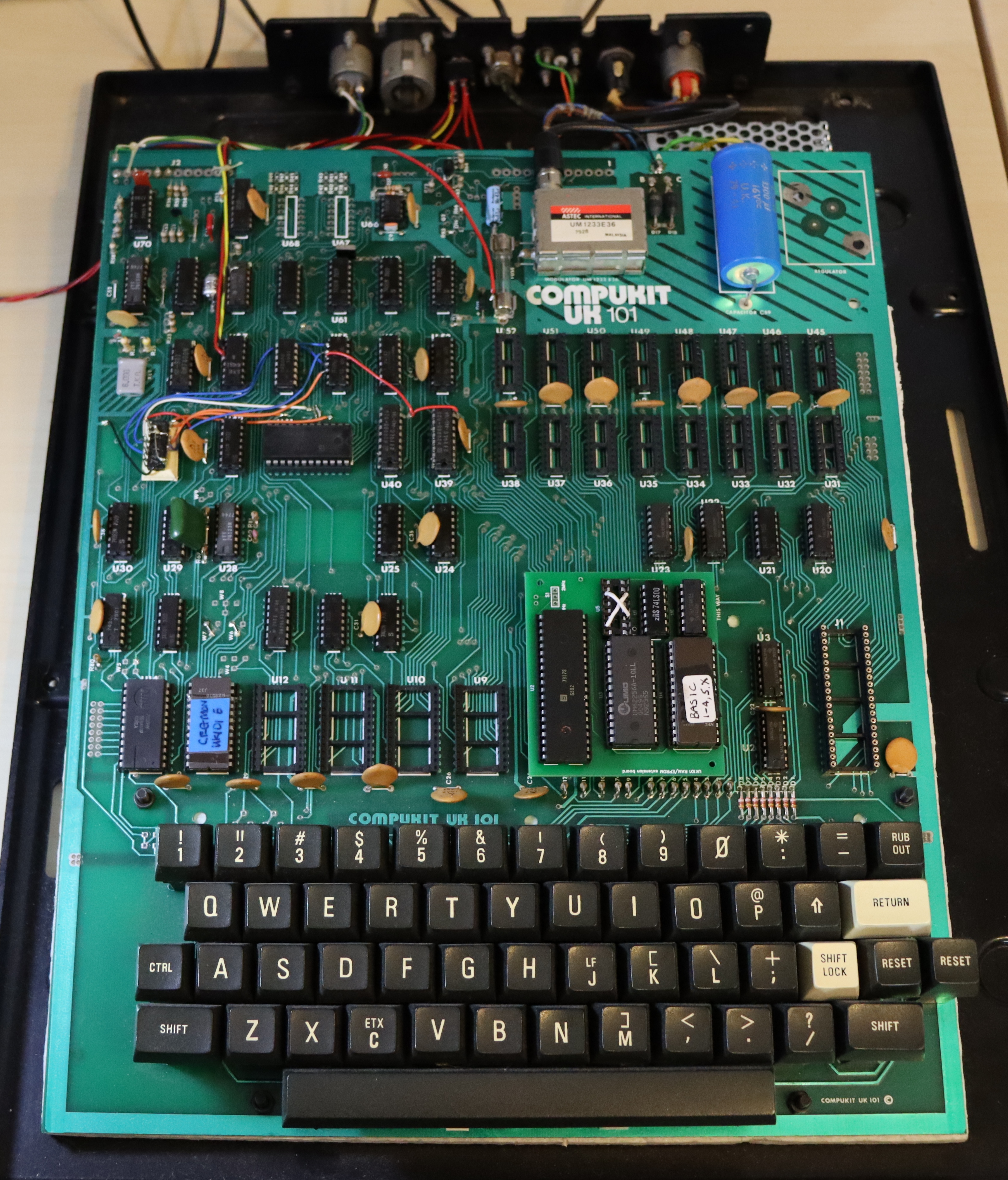
The motherboard was very clean and virtually dust free. This view shows some of the modifications made to the original board. When the computer was obtained, a large heat sink holding a LM323 5v regulator was fitted at the back under the motherboard overhang along with the original 9v mains transformer. The LM323 had never been fitted to the original position at the top right hand corner; enthusiasts generally did not fit the regulator here as the supplied heat sink was inadequate and ran very hot. The analogue power supply was later removed and replaced by a Meanwell switch mode PSU giving 5v at 5A. This provided a more accurate 5v and a 66% increase in current availability. This new PSU runs quite cool. The RAM sockets are empty because the computer was upgraded to 32K of RAM using a 62256 static RAM chip on the small circuit board plugged into the CPU socket. Not only did this upgrade increase the RAM but also the current drain was dramatically reduced, contributing to the cool running. Similarly the 2K ROM sockets holding BASIC were removed and BASIC placed in the 16K, 27128 EPROM next to the RAM chip. The wiring to the top left of the motherboard is for the VDU upgrade and the tape speed upgrade. |
 |
|
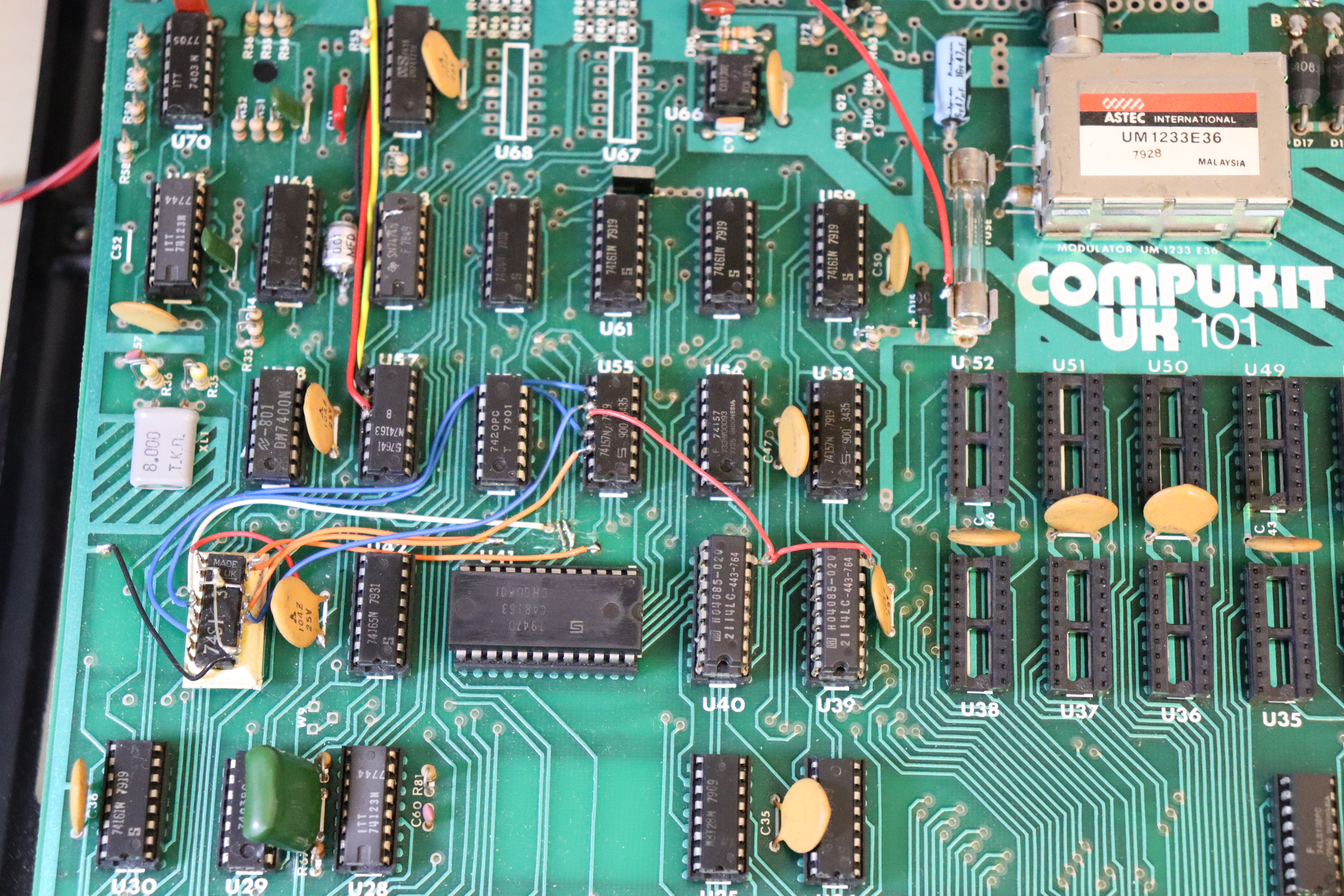
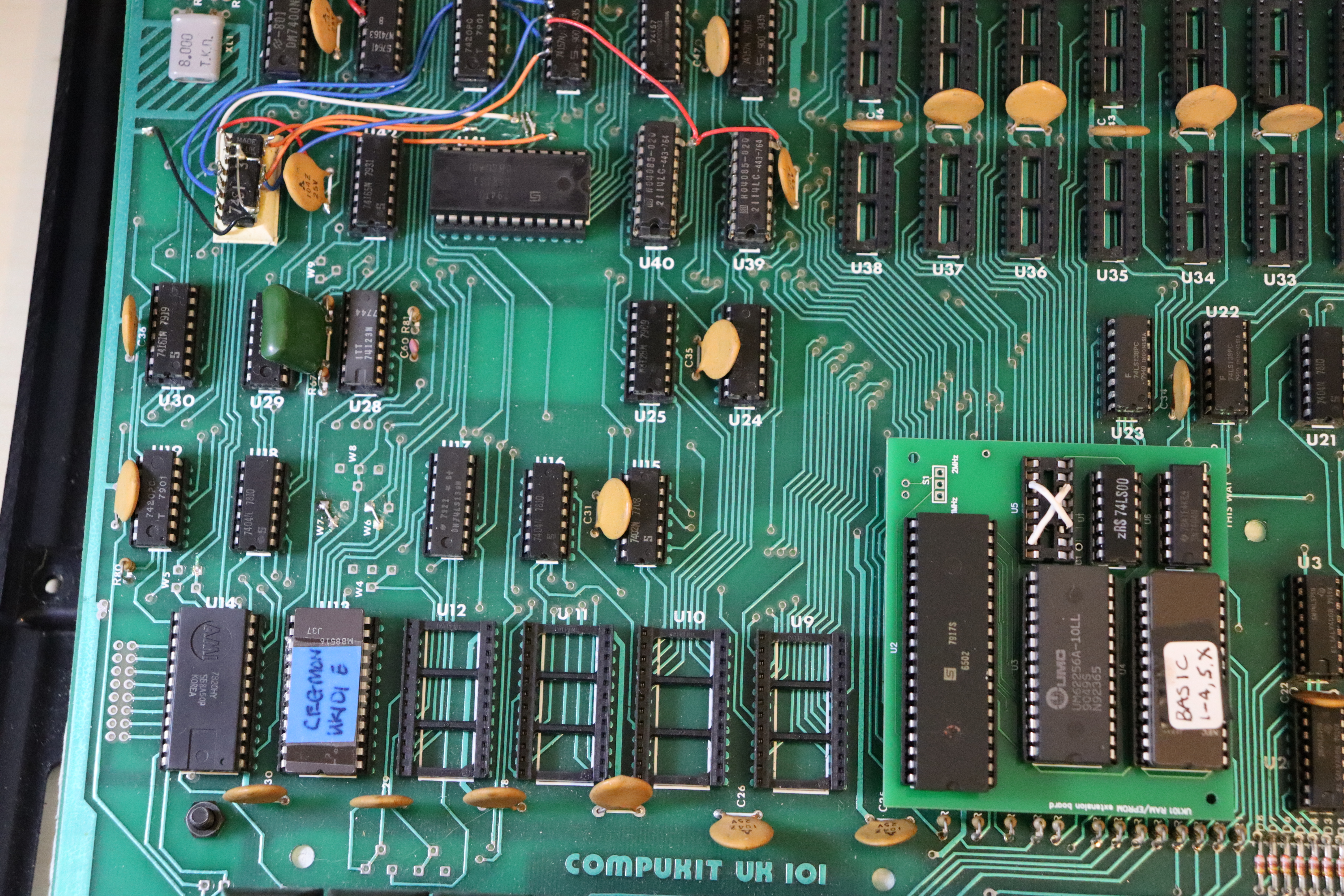
The wiring for these upgrades is shown in more detail above. The red, yellow and black wires going N-S are for the switch for the 300/600 baud cassette upgrade. The video RAM upgrade can be seen where two 2114 memory chips are piggy-backed, the red link wire being the chip select lines for the second 1K RAM. The 28-pin IC oriented E-W is the character generator ROM, which holds the character definitions. |
 |
|
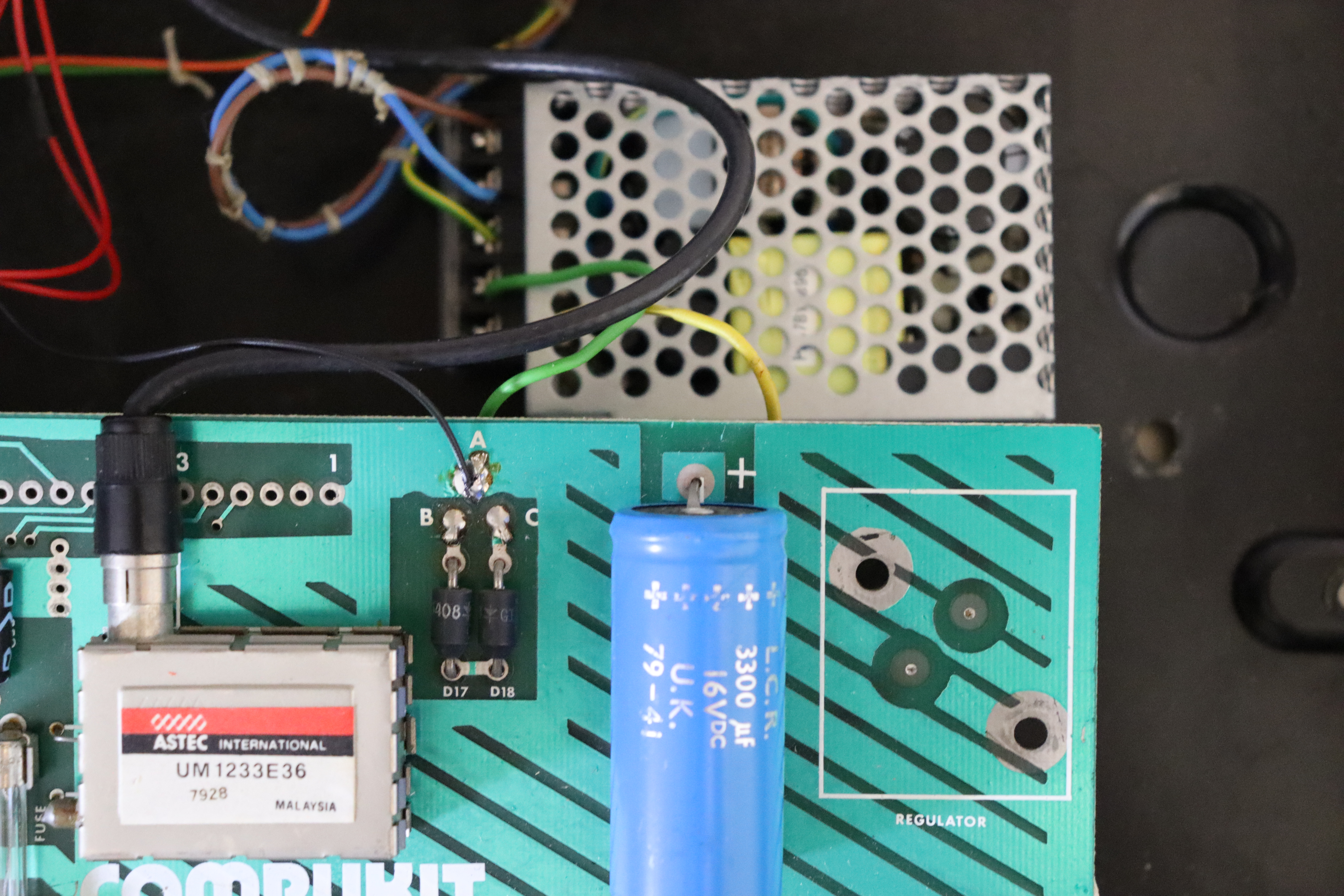
The small size of the switch mode PSU can be seen in this photograph. |
 |
|
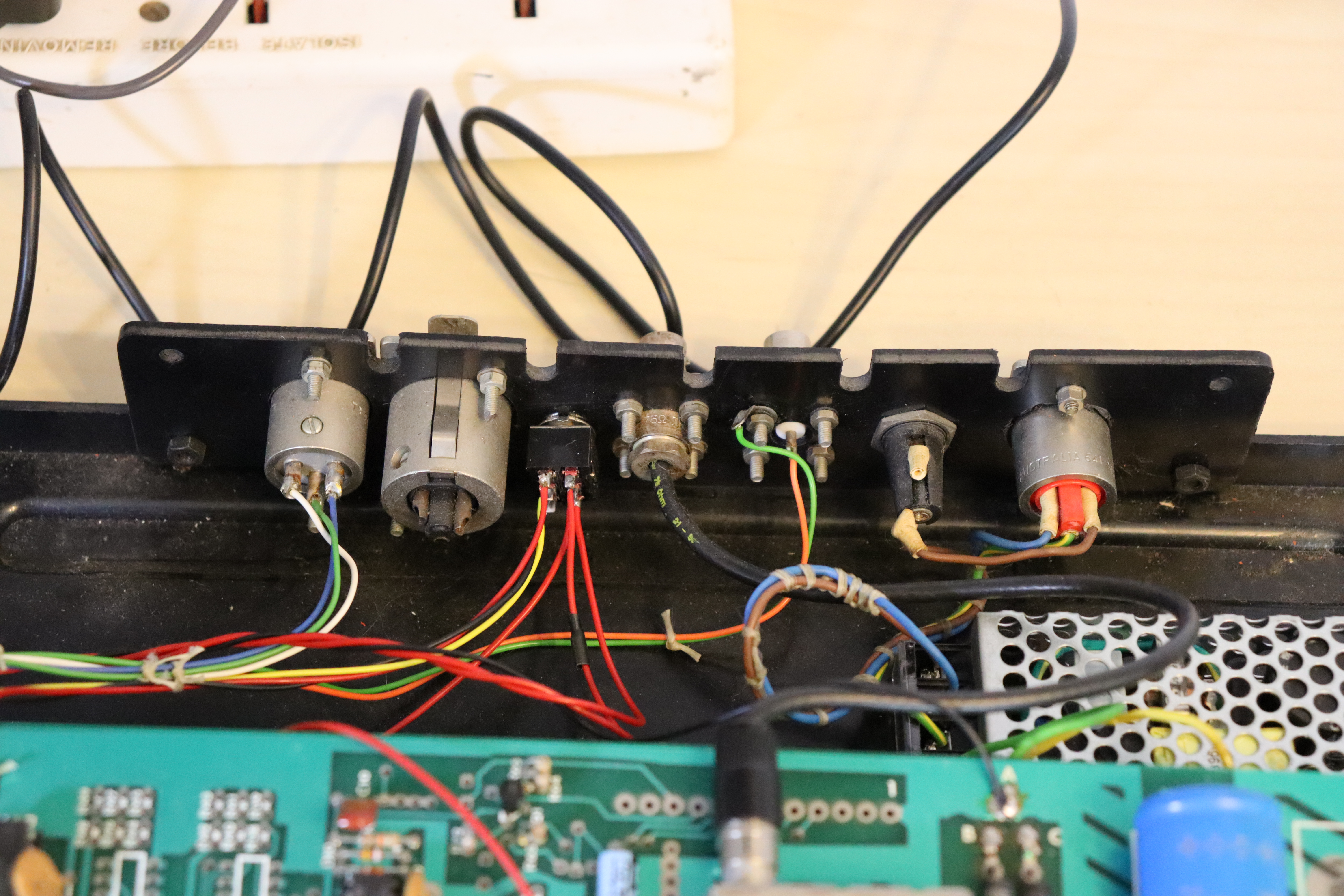
A comprehensive collection of connectors were provided at the rear of the case. They are unusual in that most are obsolete, 'professional' connectors. Mains input is via the rightmost connector, which links to a 1A fuse. Next to the fuse is the video output BNC connector and next to that a male BNC connector for the UHF output. The switch is used to switch between 300 and 600 baud for the cassette interface. The red wires on the right side are used to switch the green LED on or off to indicate 600 baud is being used. Connection to the cassette recorder is via the leftmost connector. |
 |
|
A further view of modifications to the motherboard show the Cegmon monitor and the extra circuit board in the CPU socket, which provides 32K of RAM and a 16K EPROM. 12K of the EPROM are used, containing BASIC 1 - 4, BASIC 5 and BASIC X. |
| UK101 home page |
|
© 2018 - 2026 flaxcottage.com |